
Completed view of the engine cowling and nose bowl installation.

The installation of the engine cowling begins with orienting the nose bowl to the back of the prop/spinner flange.

The goal is to establish a gap between the nose bowl and the prop/spinner flange of no more than 1/2", and no less than 1/4". I cut a 3/8" sheet of plywood to use as a spacer. If I were to do it again, I would cut the spacer a bit larger than the diameter of the prop/spinner flange. I cut mine the same size as the flange and had to keep adjusting it.

The spacer is clamped to the flange. The top half of the nose bowl is temporarily attached (wood screwed) from the back of the nose bowl to the plywood spacer. I found the center of the nose bowl and used a digital level for true level.

Then the bottom of the nose bowl is clecoed to the top of the nose bowl. Now the basis for the rest of the engine cowling is established

I did not take pictures of the four 1 1/2" x 3/4" channels used as structural members for the engine cowling. However, I did discuss these on my YouTube Channel in this episode (at the 2:10 minute mark)
The first section of the engine cowling is the top panel. This panel is .032 aluminum, the rest of the engine cowling will be .025. Notice the extruded hinge on both sides for the cowl doors.

Cutting the opening for access to the oil filler and dipstick

Access door. Still need to install the latch.

Using poster board to establish the size of the bottom cowl. The bottom cowl will be permanently affixed to the bottom of the nose bowl and the bottom two C channels and will become one piece to maintain structural integrity and for ease of assembly / disassembly.


Completed bottom cowling

Bottom Nose Bowl and Bottom Cowl are now one piece.

Using poster board to establish the cowl doors

Once the door panels were cut and attached to the top hinges, I used ratchet straps to snug in place for the final fitting.


I wanted a latching system for the doors that keeps the door nice and snug. I like these old school Piper cowling latches for their retro style and function. However, these are a little bit of a challenge to install. Not many resources or instructions are available. So I looked at many examples at Oshkosh and at local fly-ins.

The spoons used in Piper latches will be integrated into the C channels. I created a jig and practiced on a spare C channel.
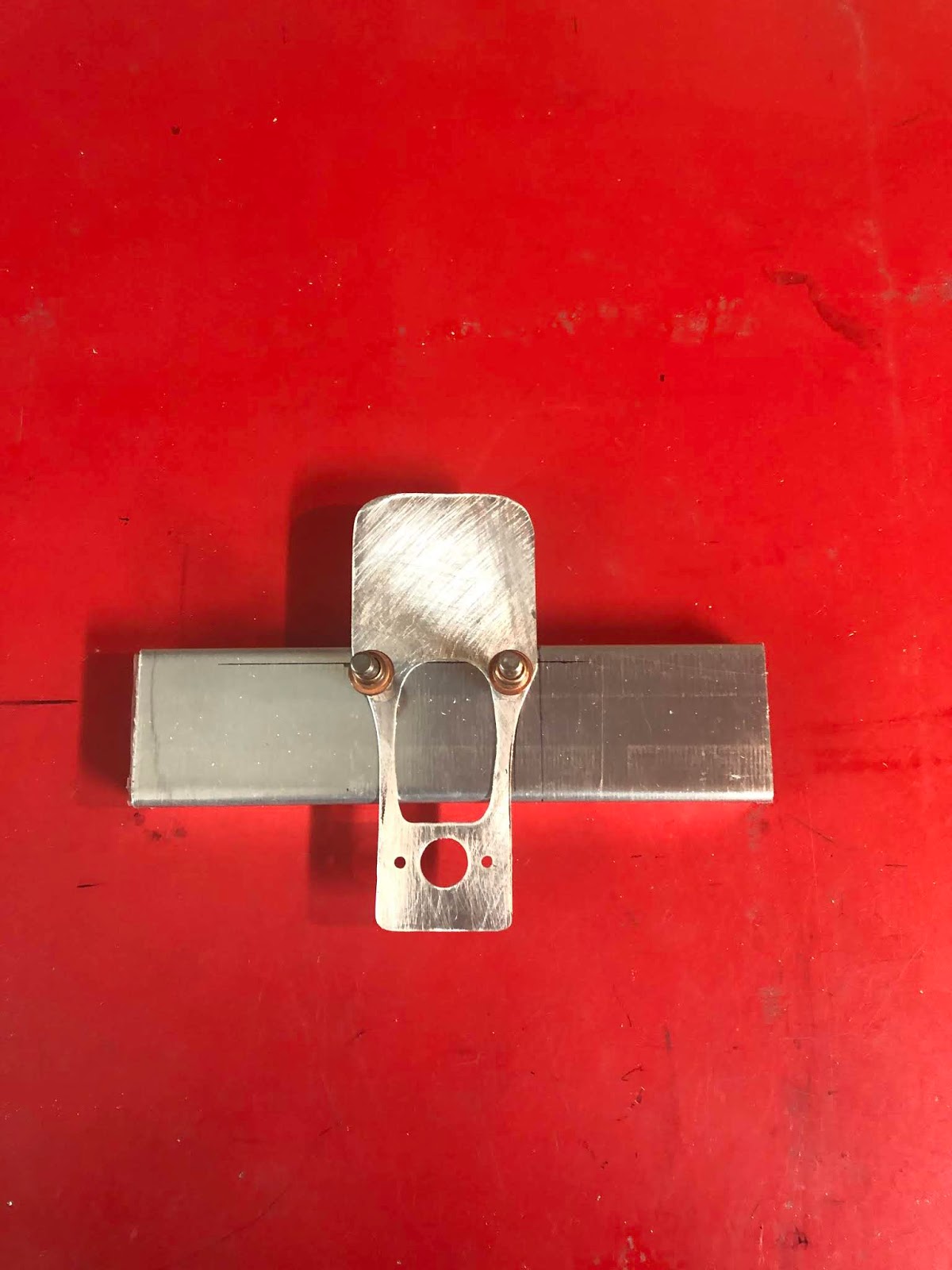

Here you can see the cut out I made to accommodate the spoon portion of the latch

This is actually upside down, but this is what the installed version will look like.

Using the same jig to establish the mounting location

Holes drilled and material will be removed where the outlines have been drawn

Completed installation. What you don't see is the aluminum angle that is mounted to the inside of the door. That angle runs almost the entire length of the door to keep the panel rigid and creates the leverage needed to cinch the panel down.

Completed installation of the nose bowl and engine cowling. Very tight!

No comments:
Post a Comment