
Below is the standard "square" air box on most Bearhawk's.

I set out to streamline the air induction system for my Bearhawk and create a round ram type inlet, like this.

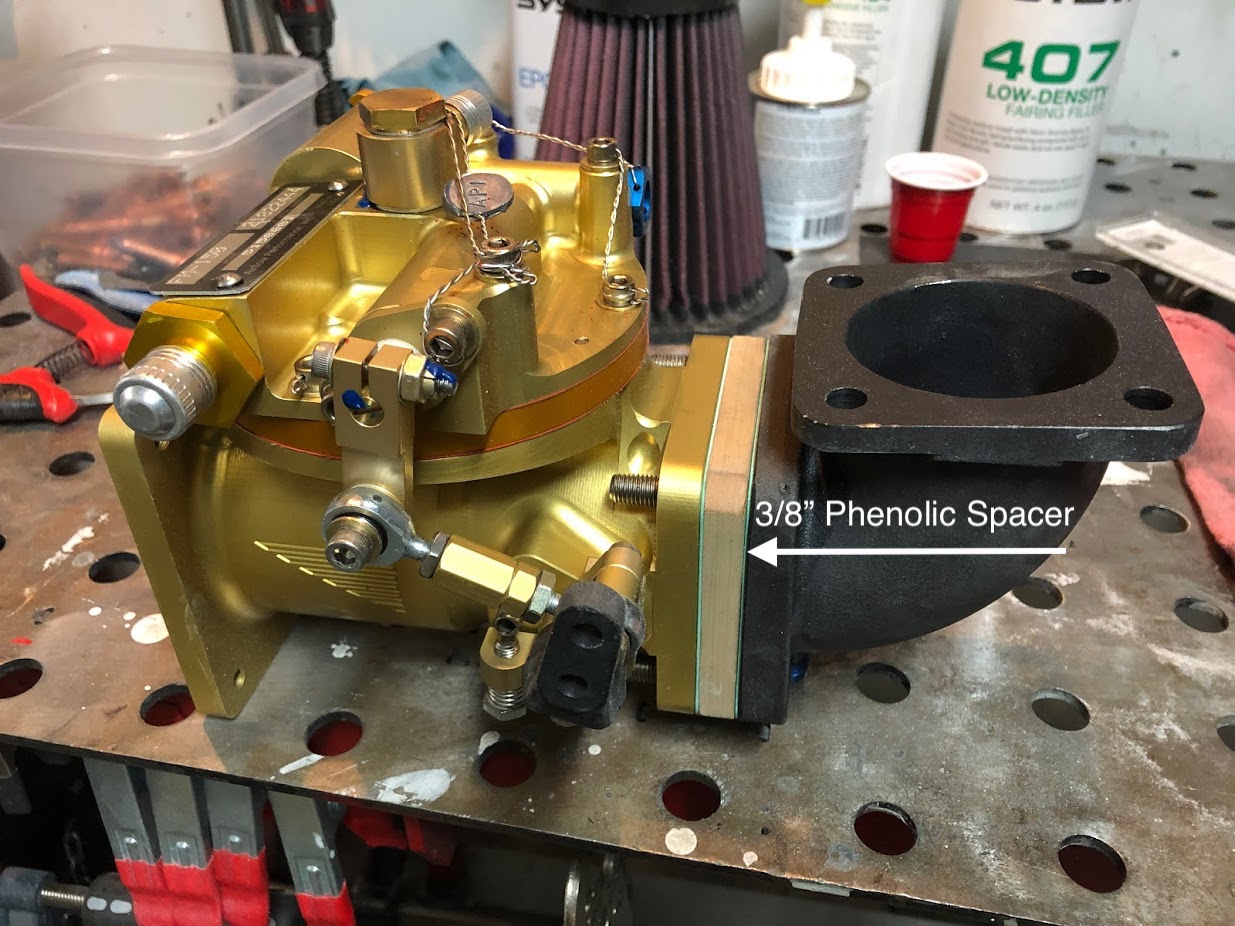
My air induction begins with the Airflow Performance FM-150 fuel controller. Airflow Performance offers a 95 degree elbow from the bottom of the sump to the back of the controller. This allows the orientation of the controller to be altered from vertical to horizontal. A control cable bracket is also installed between the elbow and the sump. A direct connection between the elbow and the back of the controller creates a conflict with the cap screws and the sump.
I used washers to get an idea how thick of a spacer would be needed to push the controller forward in order to clear the sump.

Airflow Performance sent me a 3/8" phenolic spacer.
I picked up this airbox from James Aircraft and began test fitting it between the front of the fuel controller and the bottom of the nose bowl.

The bottom of the airbox would need modified (squared off) to clear the bottom of the engine cowling.

I made a cradle for the bandsaw to make the cut.


Finished fiberglass over the cut area.
Also began a foam mold to form the back plate of the air box.

A cast of the fiberglass back plate over the foam mold.

Trimmed the filter to fit into the back plate.


Test fitting the modified airbox to the backing plate


Intake side of the airbox with the filter installed.

Next, it was time to install the aux air door.

Looking at the completed aux air door. A control cable will be attached to the steel arm at the bottom of the door.

I used a 3" aluminum tube to connect the airbox the the lower nose bowl. Fiberglass was cast around the tube. A mold release was used to keep the glass from sticking to the tube.


View from the inside. The tube serves as a coupling.

The final version. Tube trimmed. Fiberglass built up and shaped with filler. There are two #6 flush head screws that are countersunk at 3 and 9 o'clock inside the tube. Nut plates were embedded in the fiberglass.

In this video I discuss the engine cowling, including my air induction system.
No comments:
Post a Comment